 ar
ar bg
bg hr
hr cs
cs da
da nl
nl fi
fi fr
fr de
de el
el hi
hi it
it ko
ko no
no pl
pl pt
pt ro
ro ru
ru es
es sv
sv tl
tl iw
iw id
id lv
lv lt
lt sr
sr sk
sk sl
sl uk
uk vi
vi et
et hu
hu th
th tr
tr fa
fa ms
ms hy
hy ka
ka ur
ur bn
bn mn
mn ta
ta kk
kk uz
uz ku
ku
load cell wire diagram
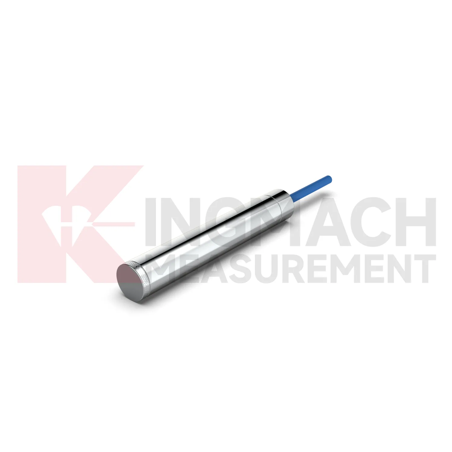
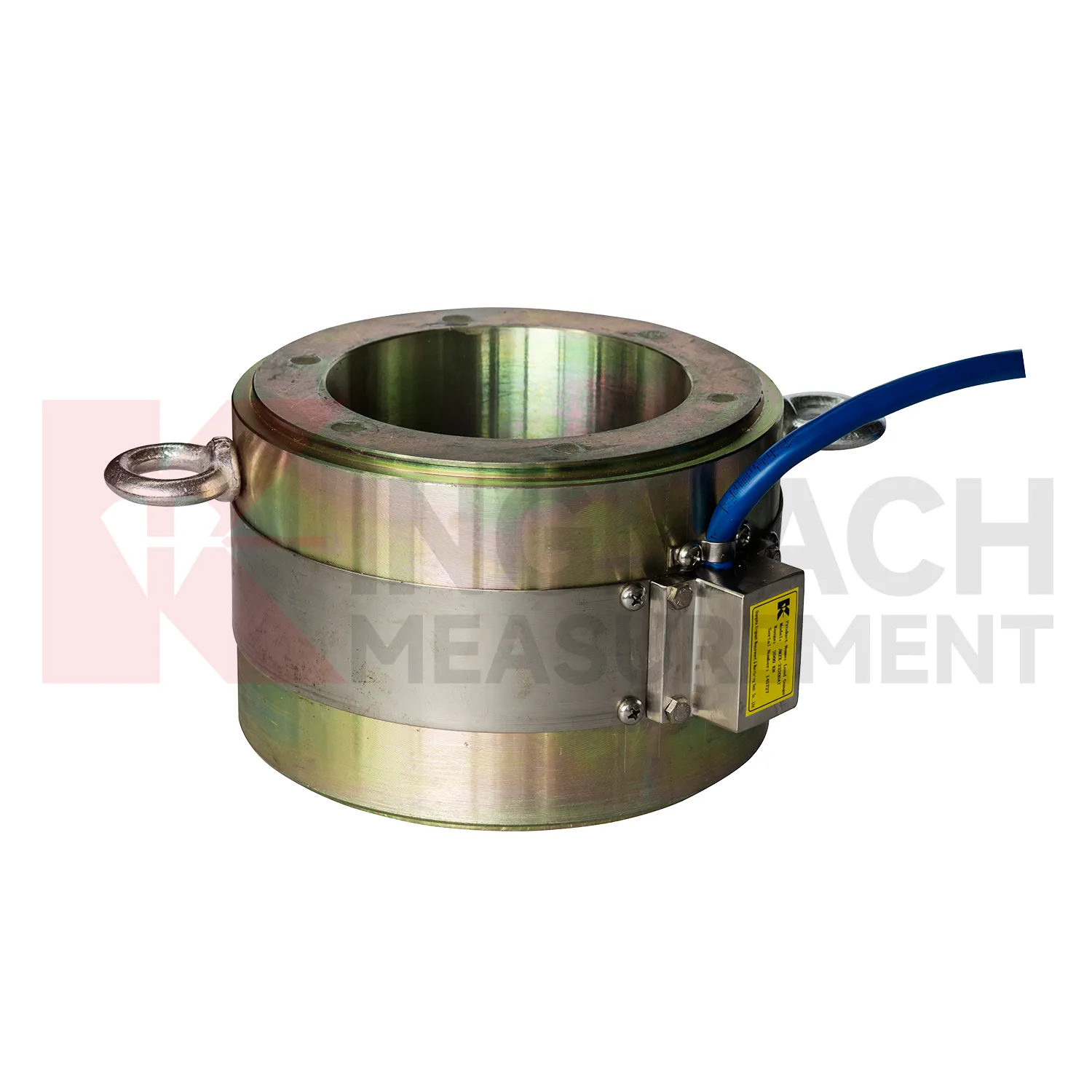
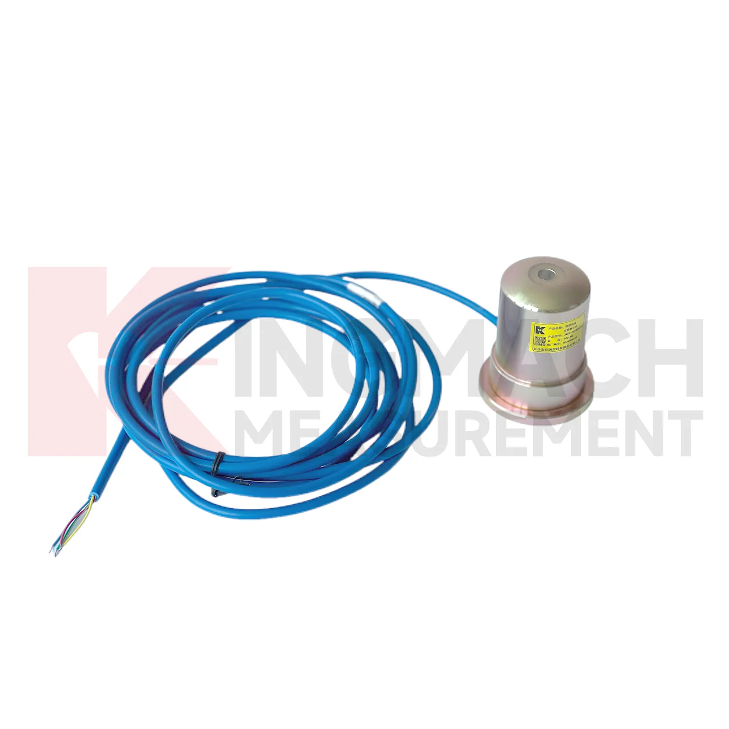
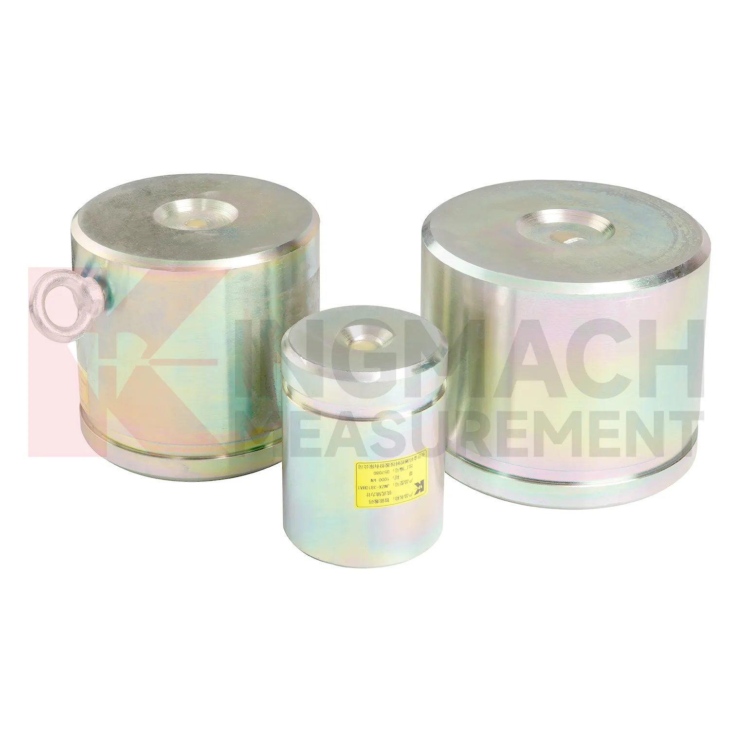
Kingmach load cell wire diagram descriptions should be read together with the data chain around the sensor. A hollow load cell can cover 500 kN to 8000 kN with a long service design, while the solid load cell line reaches 10000 kN with 0.5%FS precision. The axial force meter adds direct kN display and a 1 MPa waterproof rating for support load monitoring. Smart models include memory for calibration information, zero values, temperature data, and stored measurement records. These are not decorative features. They reduce uncertainty when many sensors are installed across a bridge, tunnel, foundation pit, dam, or rail project. Kingmach supplies readouts and data acquisition equipment, so a single instrument can be used for manual reading during installation and later connected to centralized monitoring if the owner requires it. The better specification path starts with the monitored member, expected load range, access condition, waterproof exposure, temperature swing, cable distance, and reporting method, then selects the model around those constraints. Kingmach's after-sales information also refers to warranty service, anti-static and shockproof packaging, and technical response support. Those points are useful in force monitoring because sensor damage, delivery handling, and setup questions can all affect whether the first readings are trusted.
Application of load cell wire diagram
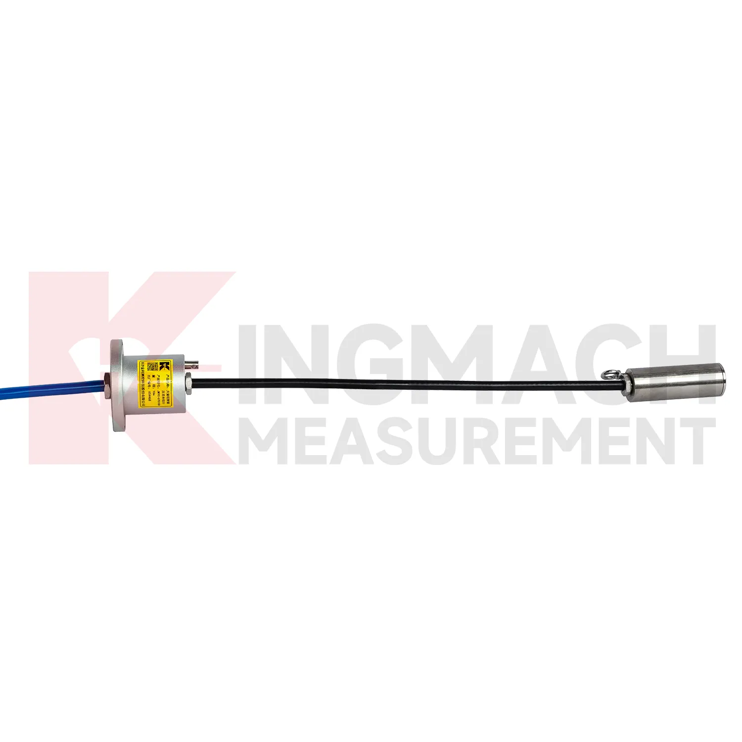
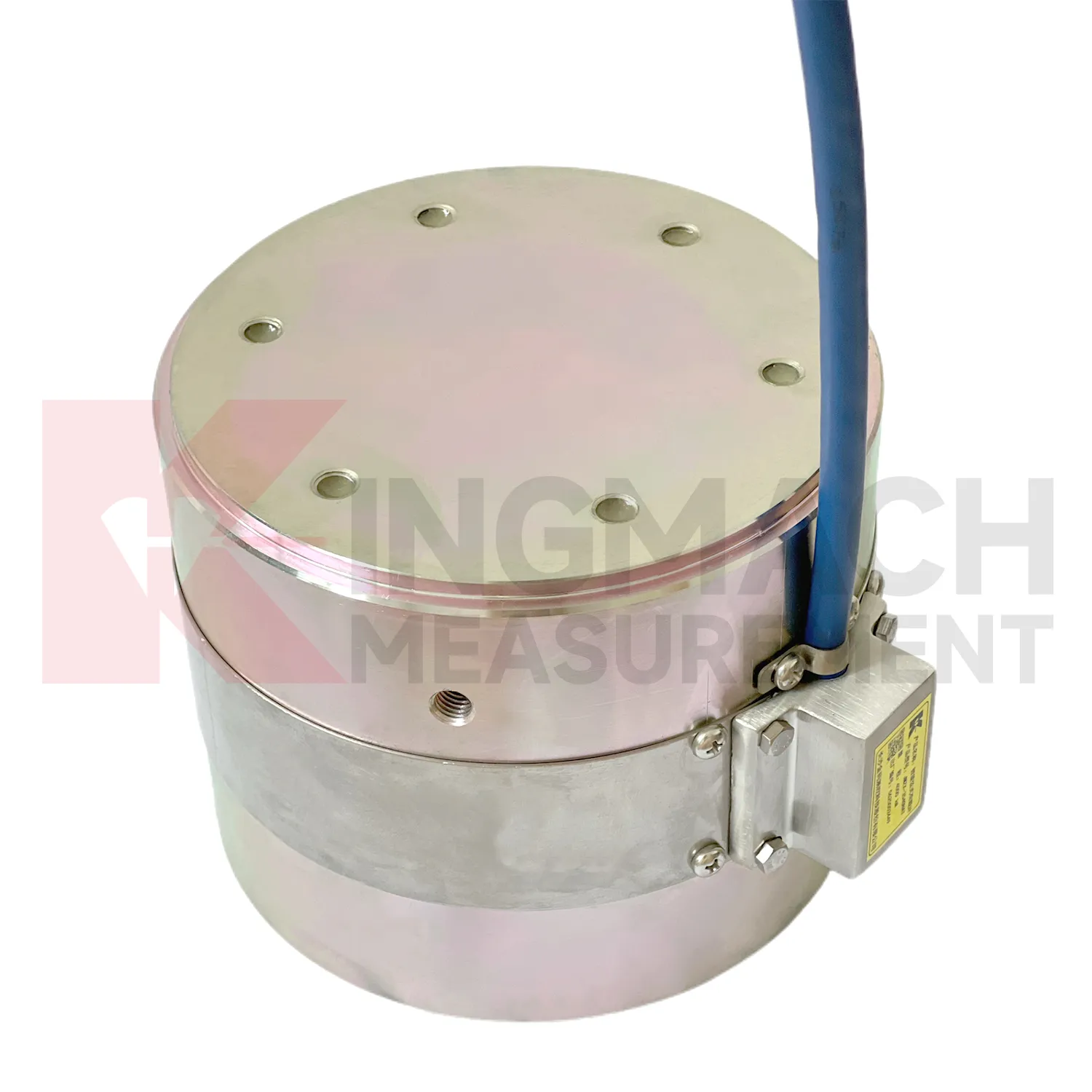
In railways, highways, and transport corridors, load cell wire diagram can monitor bridge support loads, subgrade pressure, retaining structure forces, and temporary works near active traffic. The difficulty is that access windows are short, vibration is frequent, and data gaps can create uncertainty during maintenance review. Kingmach smart load products support digital output, anti-interference transmission, built-in temperature correction, and stored model or calibration information. Solid load cells list 1000 kN to 10000 kN ranges and 0.5%FS precision, while axial force meters cover 200 kN to 3000 kN for support load points. These specifications suit high capacity structural members and staged construction near operating routes. A monitoring plan should record traffic condition, construction activity, temperature, and any maintenance event near the sensor. For owners, the value lies in trend comparison: whether support loads change after traffic opening, whether subgrade pressure rises after heavy rainfall, or whether temporary structures remain within expected force limits before removal. For transport corridors, the inspection schedule should account for possession windows, traffic vibration, and safe access. Remote acquisition may reduce field visits, but periodic visual checks still catch damaged cables, water entry, and loose junction boxes. Access for inspection should also be planned before backfilling, because later hardware checks may be harder than taking the reading itself.
The future of load cell wire diagram
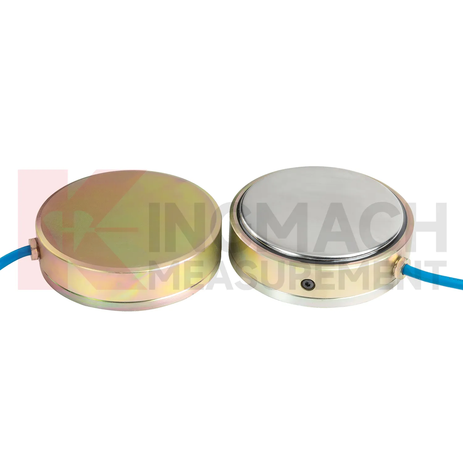
In tunnels and foundation pits, future load cell wire diagram use will move toward faster construction stage feedback. Axial force meters with 200 kN to 3000 kN ranges, 0.5%FS accuracy, direct kN display, and 1 MPa waterproofing already suit support load monitoring. The next step is pairing those readings with excavation depth, support installation time, groundwater level, wall displacement, and site progress records. LoRa or 4G gateways can reduce manual rounds where access is unsafe or work is moving too fast. Edge devices can flag missing channels, abnormal drift, or readings that changed after a cable was disturbed. This is different from a vague smart site label. It is a specific workflow where the sensor reading is checked against the work stage that should have caused it. As urban underground projects face stricter monitoring requirements, instruments that combine rugged installation, direct force output, and platform access will fit the way contractors actually manage risk.
Care & Maintenance of load cell wire diagram
For load cell wire diagram, procurement and maintenance teams should agree on records before the product reaches the site. The box should not arrive as an anonymous device. The file should contain model, range, dimensions, calibration coefficient, certificate requirements, cable length, readout method, and any custom order notes. Axial force meters are often customized, with model, range, and dimension confirmed at order and lead time often planned around 20 to 30 days. During installation, check that the delivered item matches the support diameter, bearing plate layout, and data acquisition plan. During use, keep warranty, calibration, inspection, and repair notes together with the monitoring record. Protect the sensor from overload, impact, water entry, and unauthorized rewiring. If the project changes from manual reading to automated collection, verify scaling and units before comparing new data with older values. Maintenance is easier when the administrative record is as tidy as the hardware installation. Confirm changes before handover.
Kingmach load cell wire diagram
load cell wire diagram is often selected after a project team asks where force can change without being seen. In a tunnel, the answer may be the steel support. In a bridge, it may be a cable anchor or bearing. In a foundation pit, it may be a strut, anchor, or retaining wall contact zone. In a dam, it may be an anchor system affected by water level and temperature. Kingmach's monitoring product family allows these points to be linked with settlement sensors, displacement transducers, tiltmeters, piezometers, data loggers, and software platforms. That wider context matters because load change is rarely isolated. A rising force reading becomes more meaningful when it is checked against movement, pore pressure, and construction activity. A falling force reading may point to relaxation, seating loss, or damage near the bearing surface. The instrument gives the first clue, and the surrounding data explains it. It also makes abnormal values easier to discuss with designers, contractors, and maintenance teams.
FAQ
Q: How can load cell wire diagram be connected to a monitoring platform? A: Use compatible readouts, acquisition modules, data loggers, DTUs, and software platforms according to site access, cable distance, power, and reporting requirements. Q: What makes smart models useful in large networks? A: Stored model data, calibration coefficients, zero values, temperature data, and measurement records reduce confusion across many channels. Q: Should manual readings still be kept? A: Yes, manual checks are useful after installation, maintenance, abnormal alarms, or logger changes. Q: How should alarm limits be set? A: Base them on design stage, sensor range, expected load change, temperature behavior, and nearby monitoring points. Q: What data should be reviewed together with force? A: Settlement, displacement, tilt, water level, pore pressure, rainfall, temperature, construction events, and inspection notes.
Reviews
Daniel Brown
Excellent environmental monitoring sensors. The data is consistent, and the system integrates smoothly with our existing setup.
Christopher Martinez
Very satisfied with the readouts & data loggers. User-friendly interface and supports multiple sensor inputs.
Latest Inquiries
To protect the privacy of our buyers, only public service email domains like Gmail, Yahoo, and MSN will be displayed. Additionally, only a limited portion of the inquiry content will be shown.
Isabella***@gmail.comGermany
Hello, we are evaluating weir flow meters for a water management project. Please share accuracy deta...
Mia***@gmail.comNetherlands
Dear team, we are interested in your readouts & data loggers compatible with multiple sensors. Do yo...