 ar
ar bg
bg hr
hr cs
cs da
da nl
nl fi
fi fr
fr de
de el
el hi
hi it
it ko
ko no
no pl
pl pt
pt ro
ro ru
ru es
es sv
sv tl
tl iw
iw id
id lv
lv lt
lt sr
sr sk
sk sl
sl uk
uk vi
vi et
et hu
hu th
th tr
tr fa
fa ms
ms hy
hy ka
ka ur
ur bn
bn mn
mn ta
ta kk
kk uz
uz ku
ku
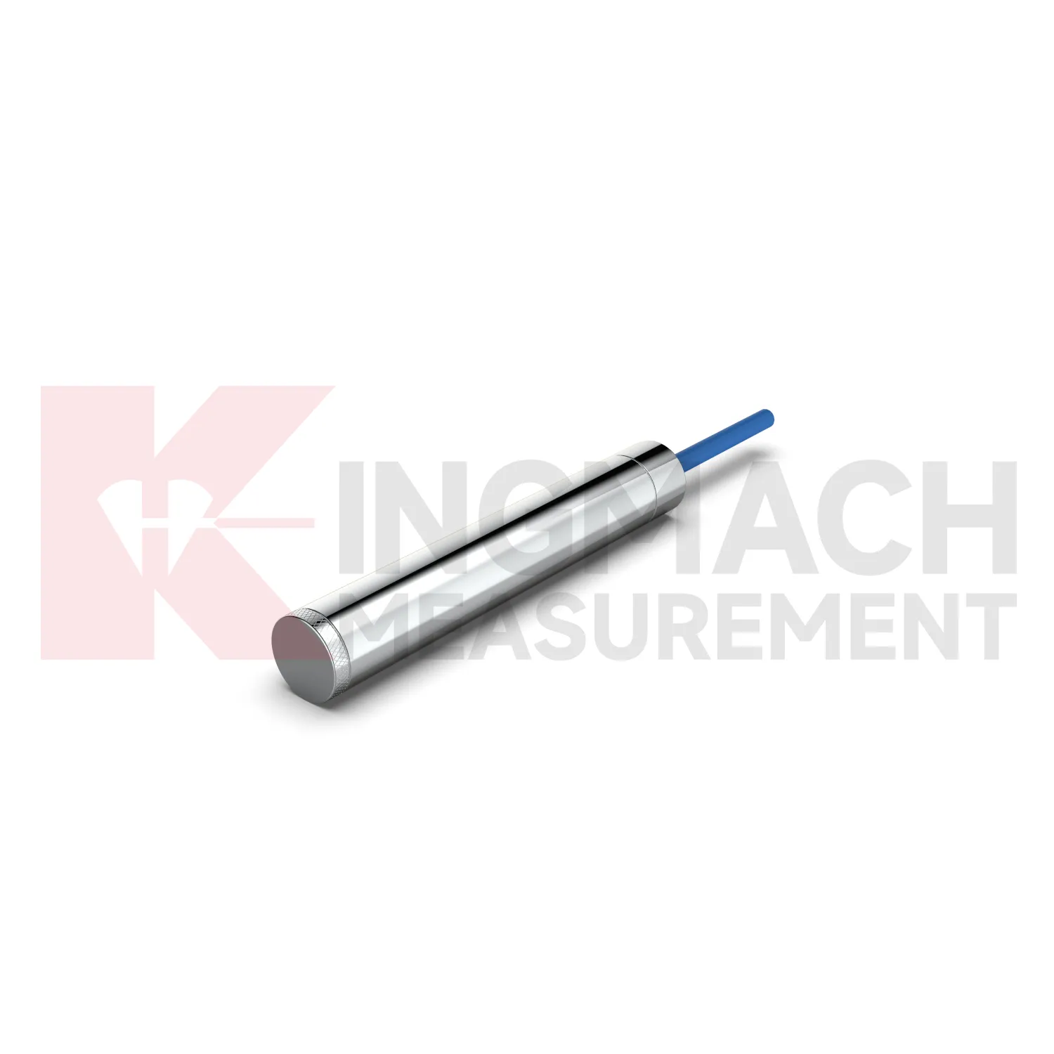
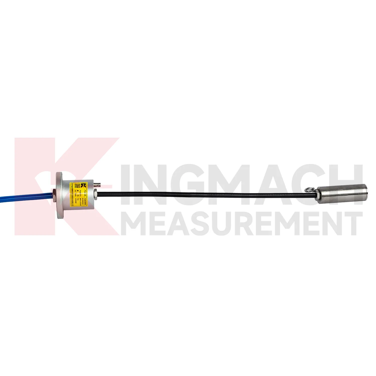
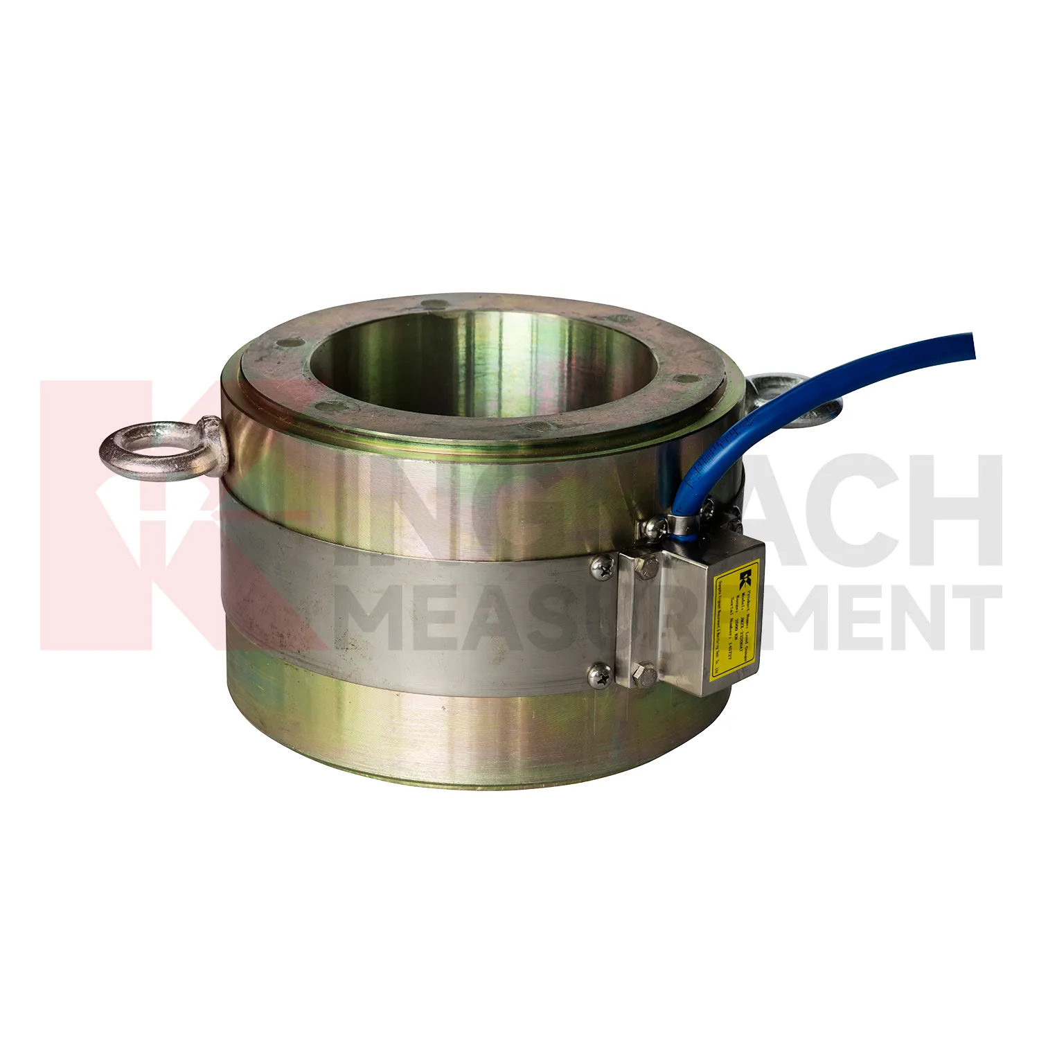
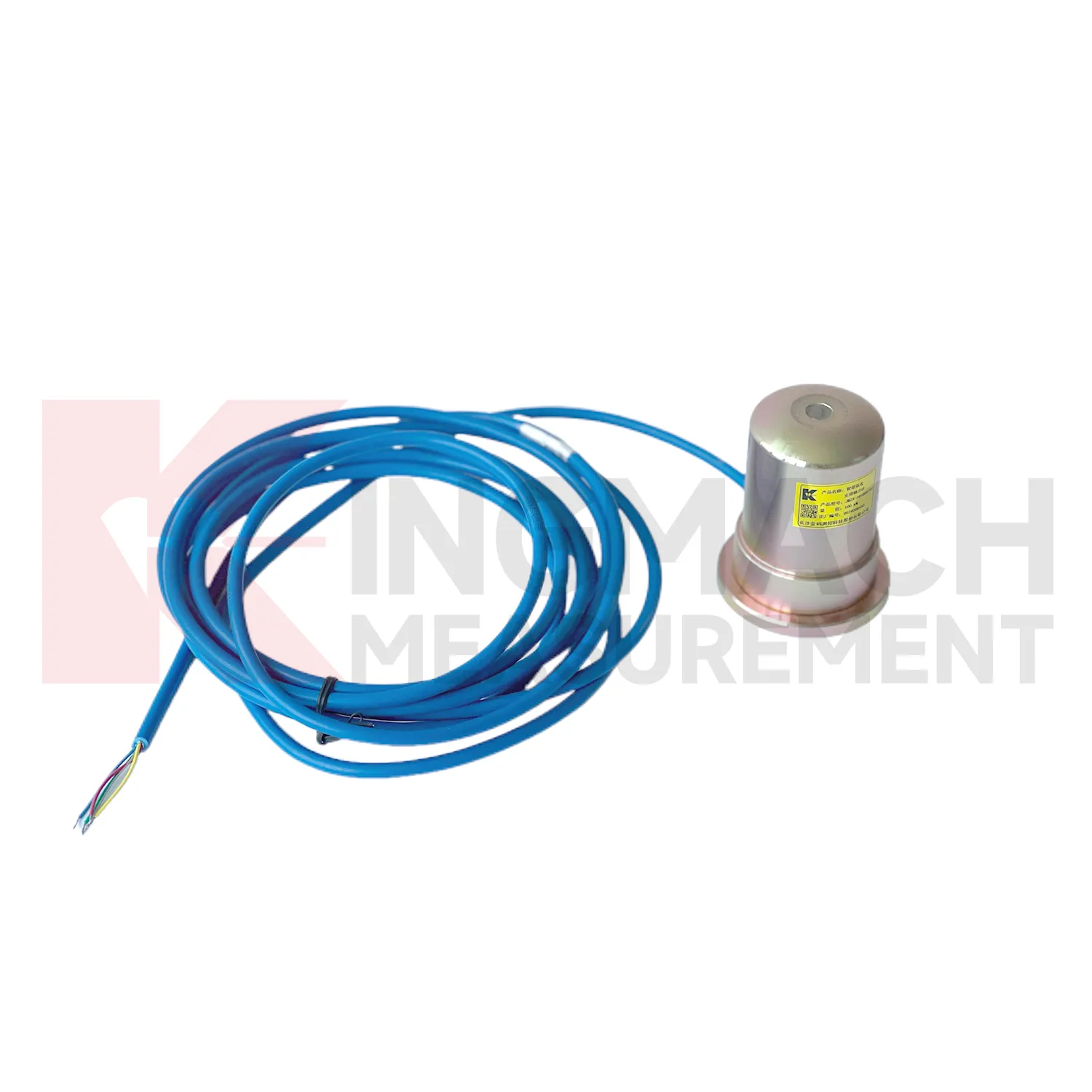
wire rope load cell
Kingmach wire rope load cell can be specified as part of a complete monitoring workflow rather than as a standalone instrument. Product pages mention manual readout compatibility, comprehensive vibrating wire readouts, automated acquisition, and storage of model or calibration information inside smart sensors. On listed models, force ranges extend from 200 kN on smaller axial force meters to 10000 kN on high capacity solid load cells, while pressure related models cover 0.3 MPa to 8 MPa. The presence of temperature correction, waterproof construction, digital output, and stable vibrating wire sensing helps the same installation work through construction and service periods. Kingmach's support range includes data loggers, instrumentation cables, and visualization software, so project teams can plan channel naming, alarm limits, report format, and maintenance inspection around the sensor from the beginning. That reduces later confusion when hundreds of monitoring points are installed across a bridge, subway, dam, slope, or foundation project. Viewed as a package, the product, readout, cable, calibration record, and software connection all affect data quality. Kingmach's catalog structure helps buyers think about that whole chain rather than treating the sensor as a loose component. For long projects, that shared record reduces confusion when installation teams, monitoring teams, and maintenance teams are not the same people.
Application of wire rope load cell
In slope, embankment, and retaining wall projects, wire rope load cell helps monitor anchor force, slide resistant pile load, earth pressure, and stress change after rainfall or groundwater variation. The practical pain point is that visible slope movement may arrive late, while load and pressure trends may start earlier. Earth pressure cells in the Kingmach range are listed from 0.3 MPa to 8 MPa, with 0.001 MPa resolution, 0.5%FS pressure accuracy, and ±0.5°C temperature accuracy. Hollow load cells for anchor force cover 500 kN to 8000 kN and include temperature correction and waterproof construction. These parameters support long term points in buried, wet, or exposed conditions. Force data should be reviewed with inclinometer, settlement, water level, rainfall, and crack observation records. If anchor force drops while displacement increases, the project team has a different problem than a temporary pressure rise after rain. The instrumentation plan should therefore connect each load point to the ground behavior it is meant to explain. On slopes, cable routes should be protected against rockfall, drainage works, vegetation clearing, and surface runoff. Those mundane details matter because a broken cable can look like a dramatic geotechnical event if the hardware is not inspected first.
The future of wire rope load cell
Future wire rope load cell design will keep moving toward lower maintenance without making the device harder to verify. Waterproof structures, high strength vibrating wires, automatic temperature correction, and smart chips already reduce field workload on Kingmach models. The next steps may include better connector sealing, self-diagnosis of signal quality, power efficient acquisition, and cleaner integration with cloud platforms. For remote dams, slopes, bridges, and rail corridors, LoRa, 4G, satellite, or wired hybrid systems may be selected according to access and power conditions. Long term data also needs stable units, channel names, calibration files, and inspection notes. Without those, a smart sensor can still produce a confusing record. Future procurement may therefore ask for sensor performance and data governance together: range, accuracy, service life, waterproof rating, memory, communication method, and exportable records. Kingmach's broad monitoring catalog is well positioned for this combined hardware and data requirement. Long life hardware still needs verifiable records around it.
Care & Maintenance of wire rope load cell
For wire rope load cell, installation quality usually determines whether later maintenance is simple or painful. Before loading, confirm the model, range, calibration coefficient, zero value, bearing surface, and cable route. Hollow load cells may cover 500 kN to 8000 kN, while solid load cells may reach 10000 kN, so capacity should be checked against both working load and possible overload. During installation, keep bearing plates flat and strong enough to avoid stress concentration, especially on axial force meters and compression load points. Protect cables from bending, pulling, welding sparks, crushing, and water entry at connectors. After the first stable reading, record temperature, channel name, instrument serial information, and site condition. During long term use, inspect sealing, cable jackets, junction boxes, and acquisition channels after rainfall, excavation changes, jacking, or impact. If a value drifts, check temperature, connector condition, zero history, and nearby sensors before assuming the instrument has failed. Document who made the check.
Kingmach wire rope load cell
wire rope load cell gives engineering teams a way to follow load behavior without dismantling the structure. In bridge bearing checks, anchor testing, steel support monitoring, pile tests, and retaining wall pressure work, the measured force can change before cracks, settlement, or visible deformation become obvious. Kingmach product information points to vibrating wire and smart sensing designs, built-in memory, automatic temperature correction, waterproof construction, and direct force display on selected models. These features matter because site readings are often taken by different people across long periods. The instrument needs to preserve its identity and calibration background even when the reading method changes from manual inspection to automated collection. The most useful force record is modest but complete: point name, model, range, coefficient, temperature, cable condition, acquisition channel, and the event that preceded the reading. That is enough to make later engineering review much less speculative. It also helps inspectors decide whether a changed value needs field checking or simple trend review.
FAQ
Q: How can wire rope load cell be connected to a monitoring platform? A: Use compatible readouts, acquisition modules, data loggers, DTUs, and software platforms according to site access, cable distance, power, and reporting requirements. Q: What makes smart models useful in large networks? A: Stored model data, calibration coefficients, zero values, temperature data, and measurement records reduce confusion across many channels. Q: Should manual readings still be kept? A: Yes, manual checks are useful after installation, maintenance, abnormal alarms, or logger changes. Q: How should alarm limits be set? A: Base them on design stage, sensor range, expected load change, temperature behavior, and nearby monitoring points. Q: What data should be reviewed together with force? A: Settlement, displacement, tilt, water level, pore pressure, rainfall, temperature, construction events, and inspection notes.
Reviews
Andrew Lee
The visualization software is intuitive and powerful. It helps us analyze monitoring data efficiently.
David Wilson
We purchased displacement transducers and settlement sensors, and the quality exceeded our expectations. Easy installation and reliable performance.
Latest Inquiries
To protect the privacy of our buyers, only public service email domains like Gmail, Yahoo, and MSN will be displayed. Additionally, only a limited portion of the inquiry content will be shown.
Harper***@gmail.comIndia
Dear Sir, we are planning to procure a complete monitoring system including strain gauges, tiltmeter...
Amelia***@gmail.comSingapore
Hello, I am looking for visualization software for monitoring system data analysis. Please let me kn...
Related product categories
- load cell zero balance
- load cell connection diagram
- load cell recalibration
- load cell testing
- load cell wiring schematic
- calibration load cells
- calibration of load cell theory
- load cell failure
- load cell technology
- strain gauge load cell wiring
- diagram 4 wire load cell wire connection
- load cell accuracy calculation